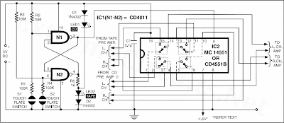
Schematic:
click for large image
When touch-plate S1 is touched (its two plates are to be bridged using a fingertip), gate N1 output (IC1, pin 3) goes high while the output of gate N2 at pin 4 goes low. This causes selection of CD outputs being connected to the power amplifier input, which is indicated by lighting of LED1. When touch-plate S2 is touched, the outputs of gates N1 and N2 toggle. That is, IC2 pin 3 is pulled ‘low’ while its pin 4 goes ‘high’. This results in selection of tape recorder outputs being connected to the input of power amplifier. This is indicated by lighting of LED2. Pin 9 is the control pin of IC2.
In the circuit, the state of multiplexer switches is shown with pin 9 ‘high’ (CD source selected). When pin 9 is pulled ‘low’, all the switches within the multiplexer change over to the alternate position to select tape player as source. Note. Although one can connect pin 7 (VEE) of IC2 to ground, but for operation with preamplifier signals going above and below ground level, one must connect it to a negative voltage (say, –1V to –1.5V) to avoid distortion.
