click for large image
Collection of electronics projects, circuit schematics design, diy hobby projects, printed circuit board softwares for students and hobbyists
IR Remote Switch
Imagine the convenience of selecting TV channels using your remote and then pointing the same remote to your switchboard to switch on/off the fan or the tubelight. Here is a simple circuit to remotely switch on/off any electrical device through a relay using the normal TV/VCR/VCP/VCD remote control unit. It works up to a distance of about 10 metres. The circuit is built around a 3-pin IR IC receiver (Siemens SFH-506-38 or equivalent) that can detect 38kHz burst frequency generated by a TV remote. (This IR receiver module has been covered earlier in many projects published in this blog.) The output pin of IR sensor goes low when it detects IR light, triggering the monostable (1-second) built around timer NE555. The output of the mono toggles the J-K flip flop, whose Q output drives the relay through SL100 npn transistor (T1).
Infrared Remote for Toy Car Motor Controller
This add-on circuit enables remote switching on/off of battery-operated toy cars with the help of a TV/video remote control handset operating at 30–40 kHz. When the circuit is energised from a 6V battery, the decade counter CD4017 (IC2), which is configured as a toggle flip-flop, is immediately reset by the power-on-reset combination of capacitor C3 and resistor R6. LED1 connected to pin 3 (Q0) of IC2 via resistor R5 glows to indicate the standby condition. In standby condition, data output pin of the integrated infrared receiver/demodulator (SFH505A or TSOP1738) is at a high level (about 5 volts) and transistor T1 is ‘off’ (reverse biased).


Gas Leakage Alarm
LPG gas leakage detector with audio visual indicator
LPG gas is supplied in pressurized steel cylinders. As this gas is heavier than air, when it leaks from a cylinder it flows along floor and tends to settle in low spots such as a basement. This can cause fire or suffocation if not dealt with.
Here is a circuit that detects the leakage of LPG gas and alerts the user through audio-visual indications. Fig. 1 shows the circuit of the gas leakage alarm. The circuit operates off a 9V PP3 battery. Zener diode ZD1 is used to convert 9V into 5V DC to drive the gas sensor module. The SEN-1327 gas sensor module from RhydoLABZ is used in this circuit. Its output goes high when the gas level reaches or exceeds certain point. A preset in the module is used to set the threshold. Interfacing with the sensor module is done through a 4-pin SIP header. Pin details of the gas sensor module are shown in Fig. 2.
Home Appliance Controller Using TV Remote
Switch home or industrial appliance On/Off with TV remote control
This circuit is designed to switch on/off any home or industrial appliance by using the TV/DVD remote controller. The circuit can be operated up to a distance of 5-10 metre depending on the remote used. The circuit consists of a step-down transformer X1 (6V-0-6V, 250mA secondary), 5V regulator 7805 (IC1), two 5V, 1 change-over (C/O) relay, a timer NE555 IC (IC2), an IR receiver module (IRX1 TSOP1738) and some discrete components. The circuit works on regulated 5V, which is derived from X1 and regulated by IC1. Home appliance is controlled either by pressing any key on the remote or by manually pressing switch S1 to ‘on’ state.

click for large image
Bicycle Horn Using Tone Generator KA2411
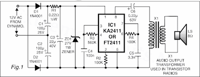
An interesting circuit of a bicycle horn based on a popular, low cost telecom ringer chip is described here. This circuit can be powered using the bicycle dynamo supply and does not require batteries, which need to be replaced frequently. The section comprising diodes (D1 and D2) and capacitors (C1 and C2) forms a half-wave voltage-doubler circuit. The output of the voltage doubler is fed to capacitor C3 via resistor R1. The maximum DC supply that can be applied to the input terminals of IC1 is 28V. Therefore zener diode ZD1 is added to the circuit for protection and voltage regulation. The remainder of the circuit is the tone generator based on IC1 (KA2411).
Luxurious Toilet Bathroom Controller
Smart controller for your toilet and bathroom. The light and fan will automatic on when someone entere toilet or bathroom and off when no person inside it.
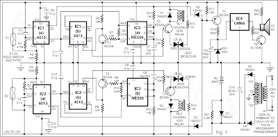
Aged persons in the house and guests often fumble while searching for the toilet and bathroom switches at night. Also, very few of us take care to switch off the lights of toilets/bathrooms after using them. The circuit given here helps to overcome both the problems. The figure shows two symmetrical circuits (one each for toilet and bathroom) sharing common power supply and a melody generator-cum-audio warning unit. The reed switches S1 and S2 are of normally-open type, operated by permanent magnets appropriately fixed to the doors of bathroom and toilet, respectively. When the doors of bathroom and toilet are closed, the reed switches are also closed, and vice versa. (Door is assumed in closed condition with nobody inside bathroom/toilet, i.e. reed switch is activated.)
Aged persons in the house and guests often fumble while searching for the toilet and bathroom switches at night. Also, very few of us take care to switch off the lights of toilets/bathrooms after using them. The circuit given here helps to overcome both the problems. The figure shows two symmetrical circuits (one each for toilet and bathroom) sharing common power supply and a melody generator-cum-audio warning unit. The reed switches S1 and S2 are of normally-open type, operated by permanent magnets appropriately fixed to the doors of bathroom and toilet, respectively. When the doors of bathroom and toilet are closed, the reed switches are also closed, and vice versa. (Door is assumed in closed condition with nobody inside bathroom/toilet, i.e. reed switch is activated.)
click for large image
Random Number Generator Game
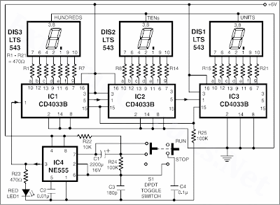
This electronic game is simulation of one-arm bandit game. Electronics hobbyists will find it very interesting. When toggle switch S1 is in ‘run’ position, all segments of 7-segment displays (DIS1 through DIS3) will light up. On turning toggle switch S1 from ‘run’ to ‘stop’ position, displayed digits will continue advancing and the final display is unpredictable. Thus the final number displayed in DIS1 through DIS3 is of random nature. The speed with which the number in 7-segment display keeps changing on flipping switch S1 from ‘run’ to ‘stop’ condition slowly decays before stopping with a random number display. To play this game, one has to obtain three identical numbers in displays DIS1 through DIS3.
The contestant would score 1 (one) point if he manages to get a final display of ‘000’, 2 points for getting ‘111’ display, 3 points for ‘222’,… and so on—up to ten points for ‘999’. He should try to score maximum possible points in fixed numbers of attempts (say, 20 to 25 attempts). Apart from using this circuit as a game for entertainment, one can use it as random number generator for any other application as well. The decay time with the given component values is around 15 seconds before the display could stop at a final random number.
Circuit diagram:
Audio Source Touch Selector
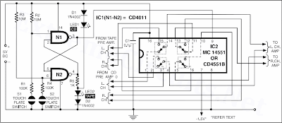
Often you need to connect output from more than one source (preamplifier) such as tape recorder/player and CD (compact disc) player to audio power amplifier. This needs disconnecting/connecting wires when you want to change the source, which is quite cumbersome and irritating. Here is a circuit that helps you choose between two stereo sources by simple touch of your hand. This circuit is so compact that it can be fixed within the audio power amplifier cabinet and can use the same power supply source. The circuit uses just two CMOS ICs and a few other componenets. The ICs used are MC14551/CD4551 (quad 2-channel analogue multiplexer) and CD4011 (quad 2-input NAND gate).
Schematic:
click for large image
Musical Touch Bell UM66
This musical call bell circuit can be operated by just bridging the gap between the touchplates with one’s fingertips. Thus there is no need for a mechanical ‘on’/‘off’ switch because the touch-plates act as a switch. Other features include low cost and low power consumption. The bell can work on 1.5V or 3V, using one or two pencil cells, and can be used in homes and offices. Two transistors are used for sensing the finger touch and switching on a melody IC. Transistor BC148 is npn type while transistor BC558 is pnp type. The emitter of transistor BC148 is shorted to the ground, while that of transistor BC558 is connected to the positive terminal.
 |
| click for large image |
| Musical Touch Bell UM66 |
High / Low Voltage Cutoff With Timer
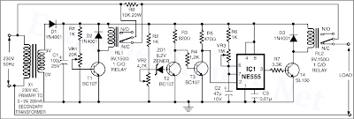
This inexpensive high / low voltage cutoff circuit can be connected to an air-conditioner/fridge or to any other sophisticated electrical appliance for its protection. Generally, costly voltage stabilizers are used with such appliances for maintaining constant AC voltage. However, due to fluctuations in AC mains supply, a regular ‘click’ sound in the relays is heard. The frequent energisation/de-energisation of the relays leads to electrical noise and shortening of the life of electrical appliances and the relay/stabilizer itself. The costly yet fault-prone stabiliser may be replaced by this inexpensive high-low cutout circuit with timer.
The circuit is so designed that relay RL1 gets energised when the mains voltage is above 270V. This causes resistor R8 to be inserted in series with the load and thereby dropping most of the voltage across it and limiting the current through the appliance to a very low value. If the input AC mains is less than 180 volts or so, the low-voltage cut-off circuit interrupts the supply to the electrical appliance due to energisation of relay RL2. After a preset time delay of one minute (adjustable), it automatically tries again. If the input AC mains supply is still low, the power to the appliance is again interrupted for another one minute, and so on, until the mains supply comes within limits (>180V AC).
Circuit diagram:
 |
| High / Low Voltage Cutoff With Timer Schematic |
Automatic Heat Detector
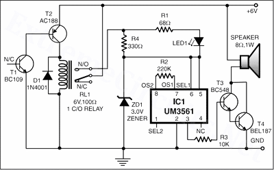
This Automatic Heat Detector circuit uses a complementary pair comprising npn metallic transistor T1 (BC109) and pnp germanium transistor T2 (AC188) to detect heat (due to outbreak of fire, etc) in the vicinity and energise a siren. The collector of transistor T1 is connected to the base of transistor T2, while the collector of transistor T2 is connected to relay RL1. The second part of the circuit comprises popular IC UM3561 (a siren and machine-gun sound generator IC), which can produce the sound of a fire-brigade siren. Pin numbers 5 and 6 of the IC are connected to the +3V supply when the relay is in energized state, whereas pin 2 is grounded.
Circuit diagram:
Circuit diagram:
 |
| Automatic Heat Detector Circuit |
Simple Alarm System
The circuit presented here is a very simple and yet highly effective alarm system for protecting an object. The circuit requires no special devices and can be built using components that you will no doubt be able to find in the junk box. The alarm-triggering element is a simple reed switch. To generate the alarm signal itself any optical or acoustic device that operates on 12 V can be used: for example a revolving light, a siren, or even both. In the quiescent state the reed switch is closed. As soon as the reed switch opens, the input to IC1.B will go low (previously the potential divider formed by R2 and R3 held the input at 5.17 V, a logic high level).
Video Switch for Intercom System IC 4060
Nowadays a lot of intercom units are equipped with video cameras so that you can see as well as hear who is at the door. Unfortunately, the camera lens is perfectly placed to serve as a sort of support point for people during the conversation, with the result that there’s hardly anything left see in the video imagery. One way to solve this problem is to install two cameras on the street side instead only one, preferably some distance apart. If you display the imagery from the two cameras alternately, then at least half of the time you will be able to see what is happening in front of the door.
Circuit diagram:
Circuit diagram:
click for larger image
Video Switch for Intercom System Circuit Diagram
Stereo LED Power (VU) Meter
BTL-type amplifiers, on the other hand, have the loudspeaker DC-coupled and ‘stretched’ between two equal, parallel, but phase-reversed outputs. The result compared to ‘CC’ is twice the voltage swing, hence quadrupling the power being fed to the same loudspeaker load. It is necessary to know to which of the two types this circuit is connected to only in order to correctly assign power levels (W) to the LEDs. CC-type have no DC voltage to ground at the outputs and return wires. The return wires are actually connected to the common ground (negative).
Real RS232 For Laptop/Notebook PCs
Many Metex DVMs feature a serial interface (RS232) which enables measured values to be copied to a PC for processing. Although this works just fine with most desktop PCs, problems may arise — as the author found out the hard way — when a laptop PC like the IBM Thinkpad 370C is hooked up to the Metex DVM. The cause of the problems is the limited voltage swing of just ±5V on the 370C’s serial interface. This is simply not enough for the Metex DVM, which will appear ‘deaf’ to the laptop.
Microscope 2.5-D Lighting
Interesting, surprising as well as scientifically useful visual effects can be obtained by employing colored LEDs instead of the normal lamp fitted in the lighting assembly in a microscope base. Of course, the lamp can be simply replaced by a white LED with appropriate changes in the supply current/voltage etc., but it is more interesting to have three colors available — here, red, green and orange (amber) which are individually adjustable for intensity. The dashed line around LEDs D2, D3 and D4 indicates that they are fitted in a 10 mm long section of 1-inch plastic (PVC) pipe.
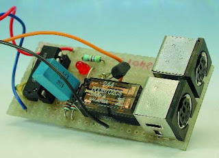
Two Keyboards on one PC
This circuit does the exact opposite of what most of this type of changeover switches attempt to do. Usually a changeover switch is used with two PCs and one keyboard. This version however makes it possible to operate one PC with two keyboards.
K1 is connected to the PC for this purpose while K2 and K3 are connected to two keyboards. The data outputs of the keyboards are high in the idle state. As soon as a key is pressed the keyboard will serially transmit the data. The data line will now also be low from time to time.
K1 is connected to the PC for this purpose while K2 and K3 are connected to two keyboards. The data outputs of the keyboards are high in the idle state. As soon as a key is pressed the keyboard will serially transmit the data. The data line will now also be low from time to time.
Overheat Detector Alarm LM35
At the heart of this over heat detector circuit is a precision integrated temperature sensor type LM35 (IC1), which provides an accurately linear and directly proportional output in mV, over the zero to +155 degrees C temperature range.
The LM35 develops an output voltage of 10 mV/K change in measured temperature. Designed to draw a minimal current of its own, the LM35 has very low self heating in still air. Here the output of the LM35 is applied to the non-inverting input of a comparator wired around a CA3130 opamp (IC2). A voltage divider network R3-P1 sets the threshold voltage, at the inverting input of the opamp. The threshold voltage determines the adjustable temperature trip level at which the circuit is activated.
Circuit diagram:
Overheat Detector Alarm/Switch Circuit Diagram
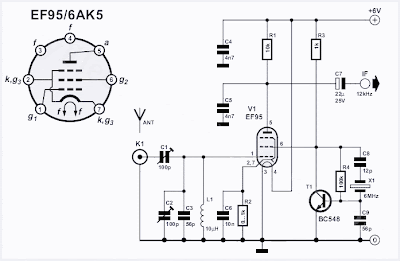
DRM Direct Mixer EF95/6AK5
This hybrid DRM receiver with a single valve and a single transistor features good large-signal stability. The EP95 (US equivalent: 6AK5) acts as a mixer, with the oscillator signal being injected via the screen grid. The crystal oscillator is built around a single transistor.
Converting a DCM Motor
We recently bought a train set made by a renowned company and just couldn’t resist looking inside the locomotive. Although it did have an electronic decoder, the DCM motor was already available 35 (!) years ago. It is most likely that this motor is used due to financial constraints, because Märklin (as you probably guessed) also has a modern 5-pole motor as part of its range. Incidentally, they have recently introduced a brushless model. The DCM motor used in our locomotive is still an old-fashioned 3-pole series motor with an electromagnet to provide motive power. The new 5-pole motor has a permanent magnet.
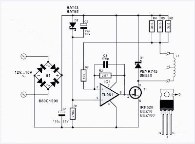
We therefore wondered if we couldn’t improve the driving characteristics if we powered the field winding separately, using a bridge rectifier and a 27 Ω current limiting resistor. This would effectively create a permanent magnet. The result was that the driving characteristics improved at lower speeds, but the initial acceleration remained the same. But a constant 0.5 A flows through the winding, which seems wasteful of the (limited) track power. A small circuit can reduce this current to less than half, making this technique more acceptable. The field winding has to be disconnected from the rest (3 wires).
We therefore wondered if we couldn’t improve the driving characteristics if we powered the field winding separately, using a bridge rectifier and a 27 Ω current limiting resistor. This would effectively create a permanent magnet. The result was that the driving characteristics improved at lower speeds, but the initial acceleration remained the same. But a constant 0.5 A flows through the winding, which seems wasteful of the (limited) track power. A small circuit can reduce this current to less than half, making this technique more acceptable. The field winding has to be disconnected from the rest (3 wires).
 |
Converting a DCM Motor |
Incandescent Lamps Life Extender
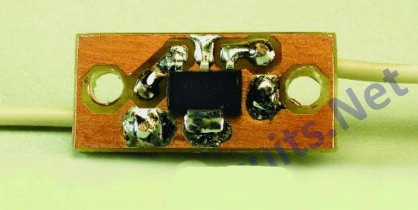
One way to extend the operating life of incandescent lamps is to reduce the voltage across the lamp by connecting something in series with it. Naturally, a series resistor is the simplest solution, but this produces unnecessary power dissipation. In order to reduce the voltage on a 100-W lamp by approximately 10 V, slightly more than 4 W must be dissipated in the resistor, and that is naturally a waste of energy. A better approach is to use a phase control circuit with a triac controller to reduce to voltage on the lamp. To reduce the voltage on the lamp by 10 V, a phase cut of approximately 44 degrees is necessary.

Garden Lighting
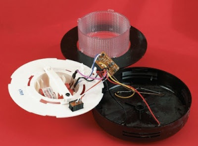
Completely ‘self-supporting’ garden lamps using solar cells as their energy source are gradually becoming more and more common. How do they actually work? We took one apart to find out. From environmental and technical considerations, buying such a solar-cell garden lamp has a lot to recommend it. It’s a great thing that the energy necessary for the lamp to burn in the evening can be drawn from the sunlight that is available for free during the day. In addition, such a lamp is enormously practical, since you can place it in any desired location in the garden without having to dig a trench through the lawn or flowerbeds.
50W Audio Amplifier Using IC TDA1562
The integrated output amplifier described in this article consists of little more than one integrated circuit. It is intended especially for use in motor vehicles and other battery-operated applications. Although it appears simple and hardly worth looking at, the amplifier can produce an appreciable audio power output. The circuit diagram in Figure 2 emphasizes how few external components are needed to construct a complete output amplifier.
Mini Lithium Torch
This mini pocket torch combines the advantages of Lithium button cells with a super-bright white LED. The lithium cells are small, have a long shelf life and have very little self-discharge. The LED has very high efficiency, an extremely long life expectancy and a modest current consumption (20mA). In combination this results in an exceptionally long-life pocket torch. It is unfortunate that a Lithium cell has a voltage of only 3 V, while a super-LED has a forward voltage of 3.5 V. One cell will not suffice and we therefore will have to connect two in series.
100W Quad Car Amplifier
This quad final amplifier is actually intended to be used in a car, but it can naturally also be used for a variety of other medium-power applications. The TDA7375A can be successfully used in all situations in which a reasonable amount of audio power is desired and only a relatively low supply voltage is available. This IC is the successor to the TDA7374B, which forms the heart of the active loudspeaker system described earlier this year. Such a quad IC amplifier is naturally an excellent choice for this application, especially since the individual amplifiers can be connected in pairs in the bridge configuration, which allows them to provide approximately four times as much power.
Two-Cell Batteries LED Torch
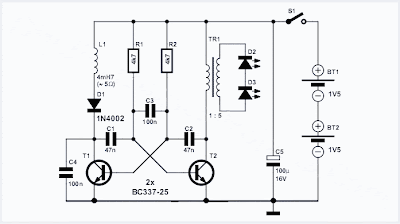
It sometimes comes as a bit of a shock the first time you need to replace the batteries in an LED torch and find that they are not the usual supermarket grade alkaline batteries but in fact expensive Lithium cells. The torch may have been a give away at an advertising promo but now you discover that the cost of a replacement battery is more than the torch is worth. Before you consign the torch to the waste bin take a look at this circuit. It uses a classic two-transistor astable multivibrator configuration to drive the LEDs via a transformer from two standard 1.5 V alkaline batteries.
The operating principle of the multivibrator has been well documented and with the components specified here it produces a square wave output with a frequency of around 800 Hz. This signal is used to drive a small transformer with its output across two LEDs connected in series. Conrad Electronics supplied the transformer used in the original circuit. The windings have a 1:5 ratio. The complete specification is available on the (German) company website at www.conrad.de part no. 516236. It isn’t essential to use the same transformer so any similar model with the same specification will be acceptable.
The operating principle of the multivibrator has been well documented and with the components specified here it produces a square wave output with a frequency of around 800 Hz. This signal is used to drive a small transformer with its output across two LEDs connected in series. Conrad Electronics supplied the transformer used in the original circuit. The windings have a 1:5 ratio. The complete specification is available on the (German) company website at www.conrad.de part no. 516236. It isn’t essential to use the same transformer so any similar model with the same specification will be acceptable.
Negative-Output Switching Regulator LM2575
There are only a limited number of switching regulators designed to generate negative output voltages. In many cases, it’s thus necessary to use a switching regulator that was actually designed for a positive voltage in a modified circuit configuration that makes it suitable for generating a negative output voltage. The circuit shown in Figure 1 uses the familiar LM2575 step-down regulator from National Semiconductor (www.national.com). This circuit converts a positive-voltage step-down regulator into a negative-voltage step-up regulator. It converts an input voltage between –5 V and –12 V into a regulated –12-V output voltage.
Note that the output capacitor must be larger than in the standard circuit for a positive output voltage. The switched current through the storage choke is also somewhat higher. Some examples of suitable storage chokes for this circuit are the PE-53113 from Pulse (www.pulseeng. com) and the DO3308P-153 from Coilcraft (www.coilcraft.com). The LM2575-xx is available in versions for output voltages of 3.3V, 5 V, 12 V and 15 V, so various negative output voltages are also possible. However, you must pay attention to the input voltage of the regulator circuit. If the input voltage is more negative than –12 V (i.e., Vin < –12 V), the output voltage will not be regulated and will be lower than the desired –12 V.
Note that the output capacitor must be larger than in the standard circuit for a positive output voltage. The switched current through the storage choke is also somewhat higher. Some examples of suitable storage chokes for this circuit are the PE-53113 from Pulse (www.pulseeng. com) and the DO3308P-153 from Coilcraft (www.coilcraft.com). The LM2575-xx is available in versions for output voltages of 3.3V, 5 V, 12 V and 15 V, so various negative output voltages are also possible. However, you must pay attention to the input voltage of the regulator circuit. If the input voltage is more negative than –12 V (i.e., Vin < –12 V), the output voltage will not be regulated and will be lower than the desired –12 V.
SDR Soundcard Tester
The key to using a soundcard successfully in digital signal processing or digital radio applications lies principally in the characteristics of the soundcard itself. This applies in particular to SDR (software defined radio) programs that turn your PC into a top-class AM/SSB/CW receiver, assuming your soundcard cooperates. If you want to experiment with SDR and avoid a lot of frustration, it is worth checking fi rst whether the PC soundcard you plan to use is suitable. There are three essential elements to success:
Circuit diagram:
- the soundcard must have a stereo line-level input;
- the card must be equipped with an input anti-aliasing filter; and
- the sample rate must be at least 48 kHz and the card must be able to cope with signals up to 24 kHz.
Circuit diagram:
Test Beeper For Audio Amplifiers
The test beeper generates a sinusoidal signal with a frequency of 1,000 Hz, a common test frequency for audio amplifiers. It consists of a classical Wien-Bridge oscillator (also known as a Wien-Robinson oscillator). The network that determines the frequency consists here of a series connection of a resistor and capacitor (R1/C1) and a parallel connection (R2/C2), where the values of the resistors and capacitors are equal to each other. This network behaves, at the oscillator frequency (1 kHz in this case), as two pure resistors. The opamp (IC1) ensures that the attenuation of the network (3 times) is compensated for.
In principle a gain of 3 times should have been sufficient to sustain the oscillation, but that is in theory. Because of tolerances in the values, the amplification needs to be (automatically) adjusted. Instead of an intelligent amplitude controller we chose for a somewhat simpler solution. With P1, R3 and R4 you can adjust the gain to the point that oscillation takes place. The range of P1 (±10%) is large enough the cover the tolerance range. To sustain the oscillation, a gain of slightly more than 3 times is required, which would, however, cause the amplifier to clip (the ‘round-trip’ signal becomes increasingly larger, after all).
Circuit diagram:
Test Beeper Circuit Diagram
Stepped Volume Control
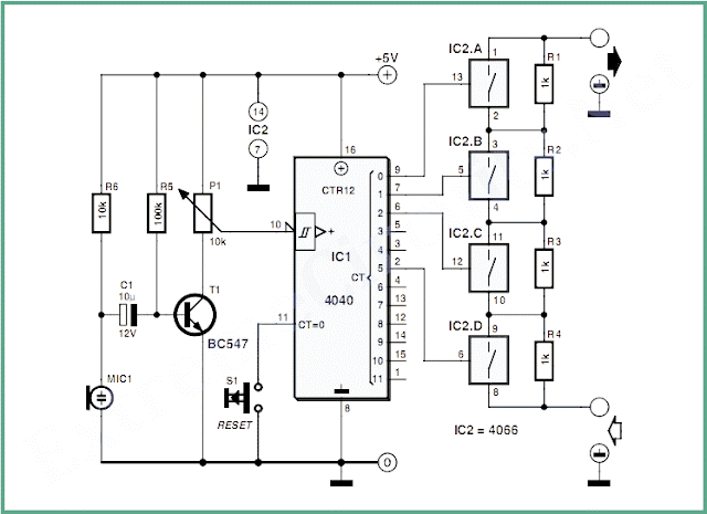
Louder music, sirens or speech in response to higher ambient noise levels? This simple circuit has the answer, and it may enable your robot to be at least as noisy or loud-mouthed as the others in an arena.
The circuit consists basically of a microphone, a level detector, a 4-state counter and four analogue switches connected to a resistive ladder network. Looking at the circuit diagram, the signal from electret microphone M1 is amplified by T1 whose collector voltage appears across a potentiometer. M1 gets its bias voltage through R4. Depending on the setting of P1, the 4040 counter will get a clock pulse when a certain noise level (threshold) is exceeded.
Circuit diagram:
Stepped Volume Control Circuit Diagram
Ultrasonic Distant Obstacle Detector
The first sensor a robot usually gets fitted with is an obstacle detector. It may take three different forms, depending on the type of obstacle you want to detect and also — indeed, above all — on the distance at which you want detection to take place. For close or very close obstacles, reflective IR sensors are most often used, an example of such a project appears elsewhere in this blog. These sensors are however limited to distances of a few mm to ten or so mm at most. Another simple and frequently-encountered solution consists of using antennae-like contact detectors or ‘whiskers’, which are nothing more than longer or shorter pieces of piano wire or something similar operating microswitches.
Circuit diagram:
Circuit diagram:
1.5 - 35 Volt DC Regulated Power Supply
Here is the circuit diagram of regulated power supply. It is a small power supply that provides a regulated voltage, adjustable between 1.5 and 35 volts at 1 ampere. This circuit is ready to use, you just need to add a suitable transformer. This circuit is thermal overload protected because the current limiter and thermal overload protection are included in the IC.
Picture of the circuit:

Picture of the circuit:

Low Cost Universal Battery Charger Schematic
Low cost solution for charging of both NiCd and NiMh batteries
Here is the circuit diagram of a low cost universal charger for NiCD - NiMH batteries. This circuit is Ideal for car use. It has ability to transform a mains adapter in to a charger . This one can be used to charge cellular phone, toys, portables, video batteries, MP3 players, ... and has selectable charge current. An LED is located in circuit to indicate charging. Can be built on a general purpose PCB or a veroboard. I hope you really like it.
Picture of the circuit:

Stereo to Mono Converter Using FET
High quality portable unit, Suitable for Subwoofer amplifiers
This simple circuit mixes two or more channels into one channel (e.g. stereo into mono). The circuit can mix as many or as few channels as you like and consume very little power. The mixer is shown with two inputs, but you can add as many as you want by just duplicating the "input sections" which are clearly visible on the schematic.
Circuit Diagram:
Mini High-Performance 12V 20W Stereo Amplifier
Amplifiers which run from 12V DC generally don’t put out much power and they are usually not hifi as well. But this little stereo amplifier ticks the power and low distortion boxes. With a 14.4V supply, it will deliver 20 watts per channel into 4-ohm loads at clipping while harmonic distortion at lower power levels is typically less than 0.03%.
This is an ideal project for anyone wanting a compact stereo amplifier that can run from a 12V battery. It could be just the ticket for buskers who want a small but gutsy amplifier which will run from an SLA battery or it could used anywhere that 12V DC is available – in cars, recreational vehicles, remote houses with 12V DC power or where ever.

Because it runs from DC, it will be an ideal beginner’s or schoolie’s project, with no 240VAC power supply to worry about. You can run it from a 12V battery or a DC plugpack. But while it may be compact and simple to build, there is no need to apologise for “just average” performance. In listening tests from a range of compact discs, we were very impressed with the sound quality.
This is an ideal project for anyone wanting a compact stereo amplifier that can run from a 12V battery. It could be just the ticket for buskers who want a small but gutsy amplifier which will run from an SLA battery or it could used anywhere that 12V DC is available – in cars, recreational vehicles, remote houses with 12V DC power or where ever.

20W Stereo Audio Amplifier
Because it runs from DC, it will be an ideal beginner’s or schoolie’s project, with no 240VAC power supply to worry about. You can run it from a 12V battery or a DC plugpack. But while it may be compact and simple to build, there is no need to apologise for “just average” performance. In listening tests from a range of compact discs, we were very impressed with the sound quality.
Audio Level Adapter
The problem that this circuit is designed to solve appeared when the author was installing a new radio in his Audi A3. The new radio had four outputs for loudspeakers and a line-level output for a subwoofer. However, the A3 as delivered from the factory already has an amplifier for the rear loudspeakers, as well as the pre-installed subwoofer, in the boot space. The original Audi radio therefore has only line-level outputs for the rear loudspeakers. So, to replace the original radio without making other changes to the installed amplification system, he needed to convert the outputs of the new radio corresponding to the rear loudspeakers into line level outputs.
Most of the commercially-available adapters to do this job contain small transformers for galvanic isolation. These introduce phase shifts and create a certain amount of distortion, which the author was keen to minimize. The result is this simple adapter circuit that does not employ a transformer. The outputs of most radios available today have a differential (bridge-type) push-pull output stage. There is thus no ground output, just two outputs per channel with a 180 ° phase difference between them. If the outputs are each connected to a common point via a 100 Ω resistor, that point becomes a virtual ground.
Circuit diagram:
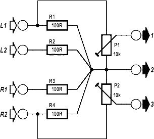

Audio Level Adapter Circuit Diagram
Subscribe to:
Posts (Atom)
