
Showing posts with label Control. Show all posts
Showing posts with label Control. Show all posts
Maximite Stepper Motor Interface
This simple circuit and program listing allows the Maximite microcomputer (SILICON CHIP, March-May 2011) to control a stepper motor. It could be expanded to allow for the control of multiple motors, with four of the Maximite’s external I/O pins used to control each motor with identical driver circuits. A ULN2003 Darlington transistor array (IC1) switches current through the stepper motor’s two windings in either direction. When one of the four Maximite output pins (8, 12, 16 & 20, corresponding to I/Os 19, 17, 15 & 13) goes high, the corresponding output pin on IC1 goes low, sinking current through a motor winding. Conversely, when these pins are high, the corresponding Darlington transistor is off and so no current flows through that portion of the winding.


IR Remote Switch
Imagine the convenience of selecting TV channels using your remote and then pointing the same remote to your switchboard to switch on/off the fan or the tubelight. Here is a simple circuit to remotely switch on/off any electrical device through a relay using the normal TV/VCR/VCP/VCD remote control unit. It works up to a distance of about 10 metres. The circuit is built around a 3-pin IR IC receiver (Siemens SFH-506-38 or equivalent) that can detect 38kHz burst frequency generated by a TV remote. (This IR receiver module has been covered earlier in many projects published in this blog.) The output pin of IR sensor goes low when it detects IR light, triggering the monostable (1-second) built around timer NE555. The output of the mono toggles the J-K flip flop, whose Q output drives the relay through SL100 npn transistor (T1).
![]()

click for large image
Infrared Remote for Toy Car Motor Controller
This add-on circuit enables remote switching on/off of battery-operated toy cars with the help of a TV/video remote control handset operating at 30–40 kHz. When the circuit is energised from a 6V battery, the decade counter CD4017 (IC2), which is configured as a toggle flip-flop, is immediately reset by the power-on-reset combination of capacitor C3 and resistor R6. LED1 connected to pin 3 (Q0) of IC2 via resistor R5 glows to indicate the standby condition. In standby condition, data output pin of the integrated infrared receiver/demodulator (SFH505A or TSOP1738) is at a high level (about 5 volts) and transistor T1 is ‘off’ (reverse biased).


Home Appliance Controller Using TV Remote
Switch home or industrial appliance On/Off with TV remote control
This circuit is designed to switch on/off any home or industrial appliance by using the TV/DVD remote controller. The circuit can be operated up to a distance of 5-10 metre depending on the remote used. The circuit consists of a step-down transformer X1 (6V-0-6V, 250mA secondary), 5V regulator 7805 (IC1), two 5V, 1 change-over (C/O) relay, a timer NE555 IC (IC2), an IR receiver module (IRX1 TSOP1738) and some discrete components. The circuit works on regulated 5V, which is derived from X1 and regulated by IC1. Home appliance is controlled either by pressing any key on the remote or by manually pressing switch S1 to ‘on’ state.

click for large image
Luxurious Toilet Bathroom Controller
Smart controller for your toilet and bathroom. The light and fan will automatic on when someone entere toilet or bathroom and off when no person inside it.
Aged persons in the house and guests often fumble while searching for the toilet and bathroom switches at night. Also, very few of us take care to switch off the lights of toilets/bathrooms after using them. The circuit given here helps to overcome both the problems. The figure shows two symmetrical circuits (one each for toilet and bathroom) sharing common power supply and a melody generator-cum-audio warning unit. The reed switches S1 and S2 are of normally-open type, operated by permanent magnets appropriately fixed to the doors of bathroom and toilet, respectively. When the doors of bathroom and toilet are closed, the reed switches are also closed, and vice versa. (Door is assumed in closed condition with nobody inside bathroom/toilet, i.e. reed switch is activated.)

Aged persons in the house and guests often fumble while searching for the toilet and bathroom switches at night. Also, very few of us take care to switch off the lights of toilets/bathrooms after using them. The circuit given here helps to overcome both the problems. The figure shows two symmetrical circuits (one each for toilet and bathroom) sharing common power supply and a melody generator-cum-audio warning unit. The reed switches S1 and S2 are of normally-open type, operated by permanent magnets appropriately fixed to the doors of bathroom and toilet, respectively. When the doors of bathroom and toilet are closed, the reed switches are also closed, and vice versa. (Door is assumed in closed condition with nobody inside bathroom/toilet, i.e. reed switch is activated.)

click for large image
Audio Source Touch Selector
Often you need to connect output from more than one source (preamplifier) such as tape recorder/player and CD (compact disc) player to audio power amplifier. This needs disconnecting/connecting wires when you want to change the source, which is quite cumbersome and irritating. Here is a circuit that helps you choose between two stereo sources by simple touch of your hand. This circuit is so compact that it can be fixed within the audio power amplifier cabinet and can use the same power supply source. The circuit uses just two CMOS ICs and a few other componenets. The ICs used are MC14551/CD4551 (quad 2-channel analogue multiplexer) and CD4011 (quad 2-input NAND gate).
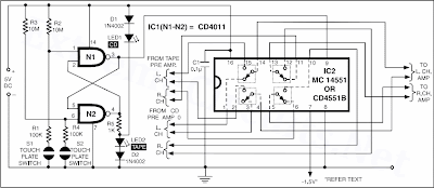
Schematic:

click for large image
High / Low Voltage Cutoff With Timer
This inexpensive high / low voltage cutoff circuit can be connected to an air-conditioner/fridge or to any other sophisticated electrical appliance for its protection. Generally, costly voltage stabilizers are used with such appliances for maintaining constant AC voltage. However, due to fluctuations in AC mains supply, a regular ‘click’ sound in the relays is heard. The frequent energisation/de-energisation of the relays leads to electrical noise and shortening of the life of electrical appliances and the relay/stabilizer itself. The costly yet fault-prone stabiliser may be replaced by this inexpensive high-low cutout circuit with timer.
The circuit is so designed that relay RL1 gets energised when the mains voltage is above 270V. This causes resistor R8 to be inserted in series with the load and thereby dropping most of the voltage across it and limiting the current through the appliance to a very low value. If the input AC mains is less than 180 volts or so, the low-voltage cut-off circuit interrupts the supply to the electrical appliance due to energisation of relay RL2. After a preset time delay of one minute (adjustable), it automatically tries again. If the input AC mains supply is still low, the power to the appliance is again interrupted for another one minute, and so on, until the mains supply comes within limits (>180V AC).
Circuit diagram:
The circuit is so designed that relay RL1 gets energised when the mains voltage is above 270V. This causes resistor R8 to be inserted in series with the load and thereby dropping most of the voltage across it and limiting the current through the appliance to a very low value. If the input AC mains is less than 180 volts or so, the low-voltage cut-off circuit interrupts the supply to the electrical appliance due to energisation of relay RL2. After a preset time delay of one minute (adjustable), it automatically tries again. If the input AC mains supply is still low, the power to the appliance is again interrupted for another one minute, and so on, until the mains supply comes within limits (>180V AC).
Circuit diagram:
 |
| High / Low Voltage Cutoff With Timer Schematic |
Thermal Fan Controller, IC 741
This fan controller uses one or more ordinary silicon diodes as a sensor, and uses a cheap opamp as the amplifier. The circuit designed for 12V computer fans, as these are now very easy to get cheaply. These fans typically draw about 200mA when running, so a small power transistor will be fine as the switch. I used a BD140 (1A, 6.5W), but almost anything you have to hand will work just as well.
Circuit diagram:

Circuit diagram:

click for large image
Thermal Fan Controller Circuit Diagram
Source: ESP
12V Speed Controller Dimmer
This handy circuit can be used as a speed controller for a 12V motor rated up to 5A (continuous) or as a dimmer for a 12V halogen or standard incandescent lamp rated up to 50W. It varies the power to the load (motor or lamp) using pulse width modulation (PWM) at a pulse frequency of around 220Hz.
SILICON CHIP has produced a number of DC speed controllers over the years, the most recent being our high-power 24V 40A design featured in the March & April 2008 issues. Another very popular design is our 12V/24V 20A design featured in the June 1997 issue and we have also featured a number of reversible 12V designs.
Circuit looks like:

For many applications though, most of these designs are over-kill and a much simpler circuit will suffice. Which is why we are presenting this basic design which uses a 7555 timer IC, a Mosfet and not much else. Being a simple design, it does not monitor motor back-EMF to provide improved speed regulation and nor does it have any fancy overload protection apart from a fuse. However, it is a very efficient circuit and the kit cost is quite low.
SILICON CHIP has produced a number of DC speed controllers over the years, the most recent being our high-power 24V 40A design featured in the March & April 2008 issues. Another very popular design is our 12V/24V 20A design featured in the June 1997 issue and we have also featured a number of reversible 12V designs.
Circuit looks like:

For many applications though, most of these designs are over-kill and a much simpler circuit will suffice. Which is why we are presenting this basic design which uses a 7555 timer IC, a Mosfet and not much else. Being a simple design, it does not monitor motor back-EMF to provide improved speed regulation and nor does it have any fancy overload protection apart from a fuse. However, it is a very efficient circuit and the kit cost is quite low.
Clap Sensitive On-Off Relay
This 3V Battery operated circuit can be used to activate a relay with a hand clap. Further claps will turn-off the relay. The circuit's sensitivity was deliberately reduced, in order to avoid unpredictable operation. Therefore, a loud hand clap will be required to allow unfailing on-off switching. Q1 acts as an audio amplifier. IC1 timer, wired as a monostable, provides a clean output signal and a reasonable time delay in order to allow proper switching of the following bistable circuit. A discrete-components circuit formed by Q2, Q3 and related parts was used for this purpose, in order to drive the Relay directly and to allow 3V supply operation.
Circuit Diagram:

Circuit Diagram:

Clap Sensitive on-off Relay Circuit Diagram
Dark Activated Terrace Lamp
Compact circuit, Can be wired in parallel to existing switches
This device allows one or more lamps to illuminate at sunset and turn off at dawn.Q1 and Q2 form a trigger device for the SCR, providing short pulses at 100Hz frequency. Pulse duration is set by R2 and C1.When the light hits R1, the photo resistor assumes a very low resistance value, almost shorting C1 and preventing circuit operation. When R1 is in the dark, its resistance value becomes very high thus enabling circuit operation.
Circuit Diagram:

This device allows one or more lamps to illuminate at sunset and turn off at dawn.Q1 and Q2 form a trigger device for the SCR, providing short pulses at 100Hz frequency. Pulse duration is set by R2 and C1.When the light hits R1, the photo resistor assumes a very low resistance value, almost shorting C1 and preventing circuit operation. When R1 is in the dark, its resistance value becomes very high thus enabling circuit operation.
Circuit Diagram:
Dark Activated 220 volt AC Lamp Circuit Diagram
Subscribe to:
Posts (Atom)