
Showing posts with label Lighting. Show all posts
Showing posts with label Lighting. Show all posts
Microscope 2.5-D Lighting
Interesting, surprising as well as scientifically useful visual effects can be obtained by employing colored LEDs instead of the normal lamp fitted in the lighting assembly in a microscope base. Of course, the lamp can be simply replaced by a white LED with appropriate changes in the supply current/voltage etc., but it is more interesting to have three colors available — here, red, green and orange (amber) which are individually adjustable for intensity. The dashed line around LEDs D2, D3 and D4 indicates that they are fitted in a 10 mm long section of 1-inch plastic (PVC) pipe.

Incandescent Lamps Life Extender
One way to extend the operating life of incandescent lamps is to reduce the voltage across the lamp by connecting something in series with it. Naturally, a series resistor is the simplest solution, but this produces unnecessary power dissipation. In order to reduce the voltage on a 100-W lamp by approximately 10 V, slightly more than 4 W must be dissipated in the resistor, and that is naturally a waste of energy. A better approach is to use a phase control circuit with a triac controller to reduce to voltage on the lamp. To reduce the voltage on the lamp by 10 V, a phase cut of approximately 44 degrees is necessary.

Garden Lighting
Completely ‘self-supporting’ garden lamps using solar cells as their energy source are gradually becoming more and more common. How do they actually work? We took one apart to find out. From environmental and technical considerations, buying such a solar-cell garden lamp has a lot to recommend it. It’s a great thing that the energy necessary for the lamp to burn in the evening can be drawn from the sunlight that is available for free during the day. In addition, such a lamp is enormously practical, since you can place it in any desired location in the garden without having to dig a trench through the lawn or flowerbeds.


Mini Lithium Torch
This mini pocket torch combines the advantages of Lithium button cells with a super-bright white LED. The lithium cells are small, have a long shelf life and have very little self-discharge. The LED has very high efficiency, an extremely long life expectancy and a modest current consumption (20mA). In combination this results in an exceptionally long-life pocket torch. It is unfortunate that a Lithium cell has a voltage of only 3 V, while a super-LED has a forward voltage of 3.5 V. One cell will not suffice and we therefore will have to connect two in series.

Two-Cell Batteries LED Torch
It sometimes comes as a bit of a shock the first time you need to replace the batteries in an LED torch and find that they are not the usual supermarket grade alkaline batteries but in fact expensive Lithium cells. The torch may have been a give away at an advertising promo but now you discover that the cost of a replacement battery is more than the torch is worth. Before you consign the torch to the waste bin take a look at this circuit. It uses a classic two-transistor astable multivibrator configuration to drive the LEDs via a transformer from two standard 1.5 V alkaline batteries.
The operating principle of the multivibrator has been well documented and with the components specified here it produces a square wave output with a frequency of around 800 Hz. This signal is used to drive a small transformer with its output across two LEDs connected in series. Conrad Electronics supplied the transformer used in the original circuit. The windings have a 1:5 ratio. The complete specification is available on the (German) company website at www.conrad.de part no. 516236. It isn’t essential to use the same transformer so any similar model with the same specification will be acceptable.
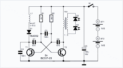
The operating principle of the multivibrator has been well documented and with the components specified here it produces a square wave output with a frequency of around 800 Hz. This signal is used to drive a small transformer with its output across two LEDs connected in series. Conrad Electronics supplied the transformer used in the original circuit. The windings have a 1:5 ratio. The complete specification is available on the (German) company website at www.conrad.de part no. 516236. It isn’t essential to use the same transformer so any similar model with the same specification will be acceptable.

Automatic Low-Power Emergancy Light
Here is portable, simple and inexpensive unit white-LED-based emergency light that offers the following advantages. 1-It is highly bright due to the use of white LEDs. 2-The light turns on automatically when mains supply fails, and turns off when mains power resumes. 3-It has its own battery charger. When the battery is fully charged, charging stops automatically. The charger power supply section is built around 3-terminal adjustable regulator IC LM317 (IC1), while the LED driver section is built around transistor BD140 (Q2).
In the charger power supply section, an input AC main is stepped down by T1 to deliver 9V, 500mA to the bridge rectifier, which comprises diodes D1 through D4. Filter capacitor C1 eliminates ripples. Unregulated DC voltage is fed to input pin 3 of IC1 and provides charging current through D5 and limiting resistor R15. By adjusting preset P1, the output voltage can be adjusted to deliver the required charging current. When the battery gets charged to 6.8V, D6 conducts and charging current from IC1 finds a path throughQT1 to ground and it stops charging of the battery. When mains power is available, the base of Q2 remains high and Q2 does not conduct. Thus LEDs are off.
In the charger power supply section, an input AC main is stepped down by T1 to deliver 9V, 500mA to the bridge rectifier, which comprises diodes D1 through D4. Filter capacitor C1 eliminates ripples. Unregulated DC voltage is fed to input pin 3 of IC1 and provides charging current through D5 and limiting resistor R15. By adjusting preset P1, the output voltage can be adjusted to deliver the required charging current. When the battery gets charged to 6.8V, D6 conducts and charging current from IC1 finds a path throughQT1 to ground and it stops charging of the battery. When mains power is available, the base of Q2 remains high and Q2 does not conduct. Thus LEDs are off.
Car-Bulb Flasher
Suitable for alerting purpose, Drives 12v Car bulbs
This astonishingly simple circuit allows one or two powerful 12V 21W car bulbs to be driven in flashing mode by means of a power MosFet. Devices of this kind are particularly suited for road, traffic and yard alerts and in all cases where mains supply are not available but a powerful flashing light are yet necessary.
Circuit Diagram:

This astonishingly simple circuit allows one or two powerful 12V 21W car bulbs to be driven in flashing mode by means of a power MosFet. Devices of this kind are particularly suited for road, traffic and yard alerts and in all cases where mains supply are not available but a powerful flashing light are yet necessary.
Circuit Diagram:
Courtesy Light IC 555
This circuit is intended to let the user turn off a lamp by means of a switch placed far from bed, allowing him enough time to lie down before the lamp really switches off. Obviously, users will be able to find different applications for this circuit in order to suit their needs.
Circuit diagram :

Circuit diagram :
Dark Activated Terrace Lamp
Compact circuit, Can be wired in parallel to existing switches
This device allows one or more lamps to illuminate at sunset and turn off at dawn.Q1 and Q2 form a trigger device for the SCR, providing short pulses at 100Hz frequency. Pulse duration is set by R2 and C1.When the light hits R1, the photo resistor assumes a very low resistance value, almost shorting C1 and preventing circuit operation. When R1 is in the dark, its resistance value becomes very high thus enabling circuit operation.
Circuit Diagram:

This device allows one or more lamps to illuminate at sunset and turn off at dawn.Q1 and Q2 form a trigger device for the SCR, providing short pulses at 100Hz frequency. Pulse duration is set by R2 and C1.When the light hits R1, the photo resistor assumes a very low resistance value, almost shorting C1 and preventing circuit operation. When R1 is in the dark, its resistance value becomes very high thus enabling circuit operation.
Circuit Diagram:
Dark Activated 220 volt AC Lamp Circuit Diagram
Subscribe to:
Posts (Atom)