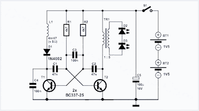
It sometimes comes as a bit of a shock the first time you need to replace the batteries in an LED torch and find that they are not the usual supermarket grade alkaline batteries but in fact expensive Lithium cells. The torch may have been a give away at an advertising promo but now you discover that the cost of a replacement battery is more than the torch is worth. Before you consign the torch to the waste bin take a look at this circuit. It uses a classic two-transistor astable multivibrator configuration to drive the LEDs via a transformer from two standard 1.5 V alkaline batteries.
The operating principle of the multivibrator has been well documented and with the components specified here it produces a square wave output with a frequency of around 800 Hz. This signal is used to drive a small transformer with its output across two LEDs connected in series. Conrad Electronics supplied the transformer used in the original circuit. The windings have a 1:5 ratio. The complete specification is available on the (German) company website at www.conrad.de part no. 516236. It isn’t essential to use the same transformer so any similar model with the same specification will be acceptable.
Collection of electronics projects, circuit schematics design, diy hobby projects, printed circuit board softwares for students and hobbyists
Showing posts with label Battery. Show all posts
Showing posts with label Battery. Show all posts
Low Cost Universal Battery Charger Schematic
Low cost solution for charging of both NiCd and NiMh batteries
Here is the circuit diagram of a low cost universal charger for NiCD - NiMH batteries. This circuit is Ideal for car use. It has ability to transform a mains adapter in to a charger . This one can be used to charge cellular phone, toys, portables, video batteries, MP3 players, ... and has selectable charge current. An LED is located in circuit to indicate charging. Can be built on a general purpose PCB or a veroboard. I hope you really like it.
Picture of the circuit:

Flashing-LED Battery-status Indicator
Flashing-LED Battery-status Indicator will signals when an on-circuit battery is exhausted. It works with 5V to 12V operating voltage
A Battery-status Indicator circuit can be useful, mainly to monitor portable Test-gear instruments and similar devices. LED D1 flashes to attire the user's attention, signaling that the circuit is running, so it will not be left on by mistake. The circuit generates about two LED flashes per second, but the mean current drawing will be about 200µA. Transistors Q1 and Q2 are wired as an uncommon complementary astable multivibrator: both are off 99% of the time, saturating only when the LED illuminates, thus contributing to keep very low current consumption.
Circuit operation:
The circuit will work with battery supply voltages in the 5 - 12V range and the LED flashing can be stopped at the desired battery voltage (comprised in the 4.8 - 9V value) by adjusting Trimmer R4. This range can be modified by changing R3 and/or R4 value slightly. When the battery voltage approaches the exhausting value, the LED flashing frequency will fall suddenly to alert the user. Obviously, when the battery voltage has fallen below this value, the LED will remain permanently off. To keep stable the exhausting voltage value, diode D1 was added to compensate Q1 Base-Emitter junction changes in temperature. The use of a Schottky-barrier device (e.g. BAT46, 1N5819 and the like) for D1 is mandatory: the circuit will not work if a common silicon diode like the 1N4148 is used in its place.
Circuit diagram:
Flashing-LED Battery-status Indicator Circuit Diagram
Subscribe to:
Posts (Atom)

